 User Help Manual
  Learn FAQ
  Send us feedback
 ")


How to Work with AI Video Segmentation in VSDC
What is Video Segmentation?
AI-video segmentation is an innovative way of managing video content by dividing it into smaller segments or shots to extract meaningful information and features. VSDC provides video segmentation as a free tool based on AI models: AI allows to accurately identify the boundaries of one or multiple objects and capture them to isolate or highlight both stationary and moving elements. This way you can cut out an object and insert it into another video, perform color correction, draw contours around characters, create masks, or apply other editing options to create unique visual effects.
Today we will show you how to work with this tool and provide examples. So, download VSDC Video Editor and let's get started!
 Download VSDC Video Editor
Adding Segmentation
- To start working with segmentation, add your mediafile to the scene. Select this file by clicking on it on the timeline and add segmentation by one of the following methods:
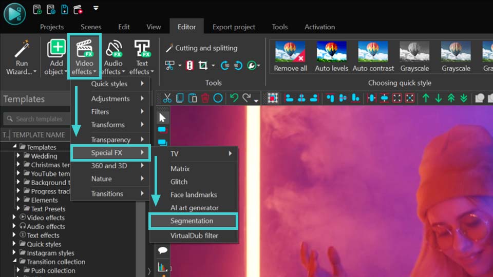
- Right-click the selected object and choose Video effects >> Special FX >> Segmentation;
- Go to the Editor tab, navigate to Video effects >> Special FX >> Segmentation.
- Then you’ll see the Object's position setting window. Adjust the parameters (if necessary) and press OK.
- Then navigate to the Properties window where you can adjust parameters, described below.
Parameters of Segmentation
There are three main groups of parameters, available in the Properties window:
- Common settings: allow you to specify the name of the added object, object creation time, object drawing duration and whether it is bound (or not) to the parent object. These are basic settings that can be applied to any object or effect.
- Adjustment settings: do not work for the Segmentation tool.
- Segmentation parameters: this section allows you to configure unique parameters of segmentation. Below in this article we are going to work with them. Let’s consider them in detail in the next part.

Starting With Segmentation
- If you are new to working with the segmentation tool, in the Segmentation parameters section you will initially see only two options: Download data model and Import data model. Click on the Download data model option to get to a web page where you can choose from 4 models to download:
- FB-SAM: This is a basic model with high accuracy in recognizing static objects in pictures. Note that it might be demanding on PC memory compared to other AI options and operate rather slowly.
- SAM-HQ: This is an advanced model, offering precise recognition of small elements. better performance with moving objects, though it is slower and demands more memory.
- EdgeSAM: This is an enhanced mode with lower RAM requirements and faster performance, perfect for processing long video files on less powerful PCs. It provides good segmentation accuracy in most projects.
- MobileSAM: This is another enhanced model featuring fast performance and low PC memory usage and a good alternative to EdgeSAM.
- After downloading the desired AI model, import it into the program by using the Import data model button. This action will update the Segmentation parameters menu, where the first option in the list will now include a Model field. This field allows you to select, download or import new AI models by clicking the icons on the right.
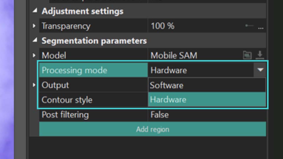
- The next step is to select the Processing mode. It determines whether to utilize your graphics card (Hardware) or your PC's resources (Software) while working with the Segmentation tool. For optimal performance, we recommend setting Hardware to reduce the load on your PC. For more information, refer to the Troubleshooting guide.
To continue working with the parameters of segmentation, you need to set the segmentation region. Here’s how to do it:
Adding Segmentation Regions
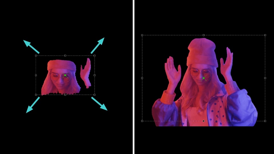
- Select the Add region button in the Properties window and choose the Include region option to mark the area on the scene containing the object for segmentation.
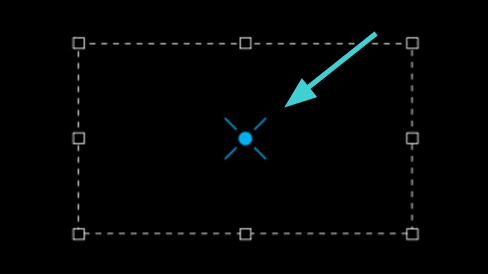
- Next, you’ll see an area defining the segmentation region in the preview window. If necessary, change the size of this area by stretching the markers or move it by dragging it with the mouse. Repeat these two steps as needed to create multiple segmentation regions.
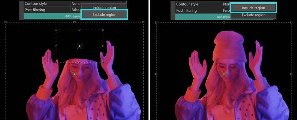
- If the added region shows an area that should be excluded, click the Add region button again in the Properties window and choose Exclude region. Position this new area over the unwanted object to remove it. NOTE: this exclusion zone must always be within the Include region and smaller than it.
Add region >> Include region Add region >> Exclude region
Fine-Tuning the Results of Segmentation
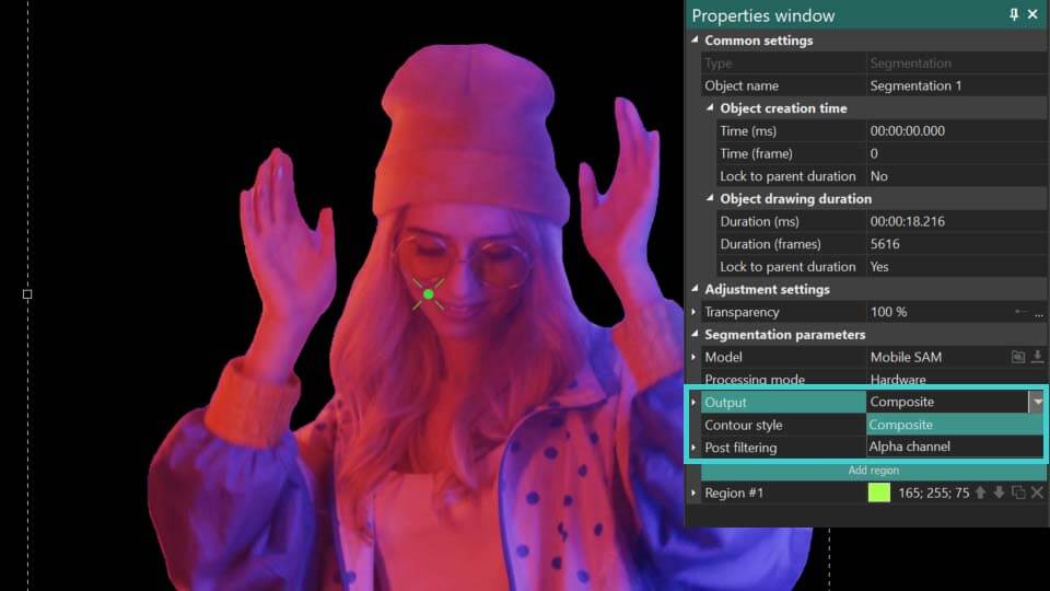
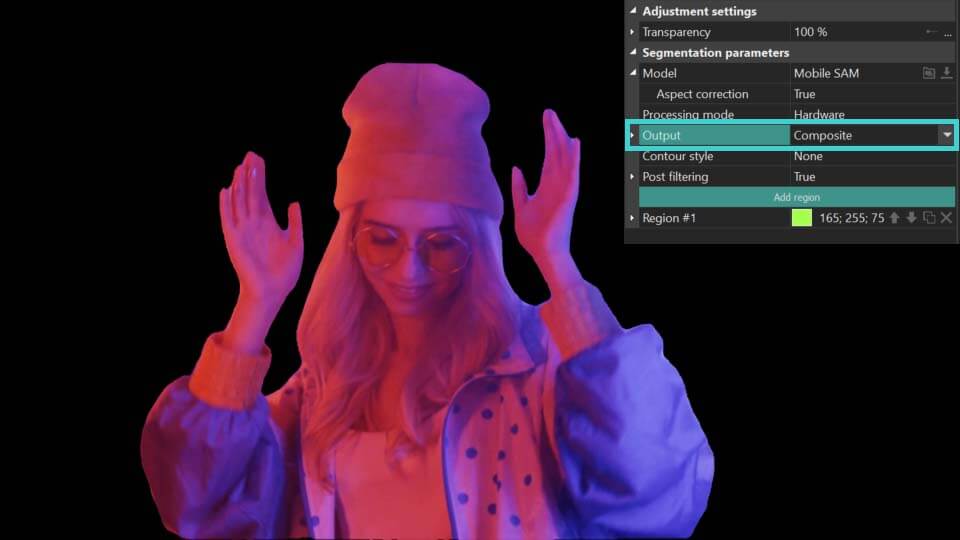
- Output: defines how the segmentation results are displayed:
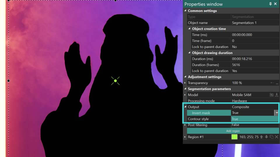
 Composite: conceals everything behind the segmented object without modifying the object itself. Additionally, it enables an Invert Mask option, which reveals the background while turning the segmented object invisible.
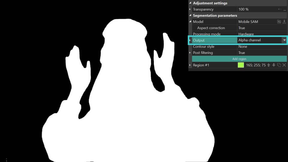
Alpha channel: highlights the segmented object in white, with all areas outside the object appearing black. It also features an Invert Mask option, which reverses this effect by coloring the object black and the surrounding area white. Colors for the mask can be customized using the Mask Color and Background Color fields.
Composite: conceals everything behind the segmented object without modifying the object itself. Additionally, it enables an Invert Mask option, which reveals the background while turning the segmented object invisible.
Alpha channel: highlights the segmented object in white, with all areas outside the object appearing black. It also features an Invert Mask option, which reverses this effect by coloring the object black and the surrounding area white. Colors for the mask can be customized using the Mask Color and Background Color fields.
- Aspect correction: can be found in the Model parameter. Refines the contour of segmented objects for more accurate results.
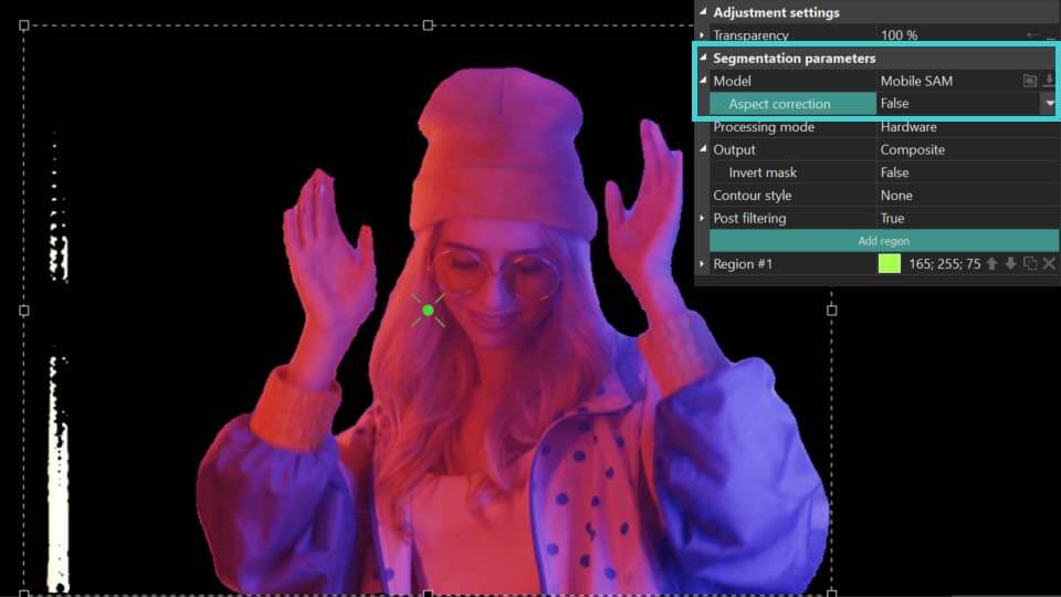
As you can see from the above example, when the Aspect correction parameter is set to True, the program more accurately determines the contour of the object itself in the segmentation area. If the result has not changed or has become worse, set it to False and use the tools described below to refine the contour of the segmented object.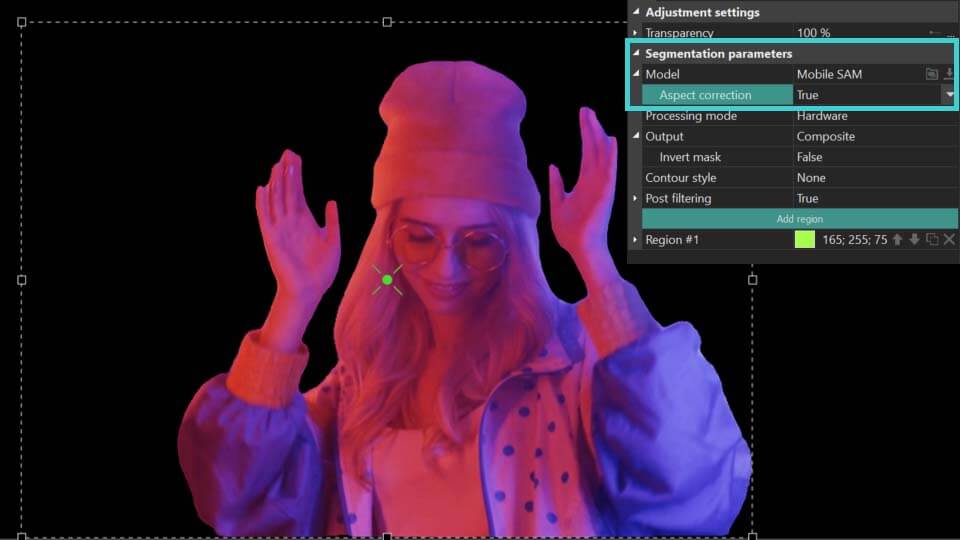
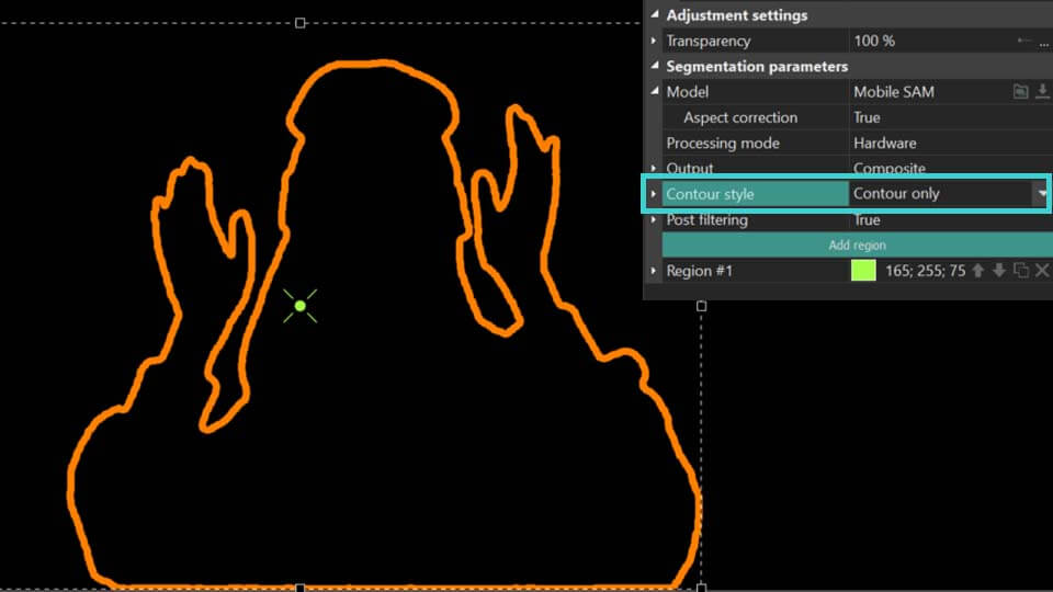
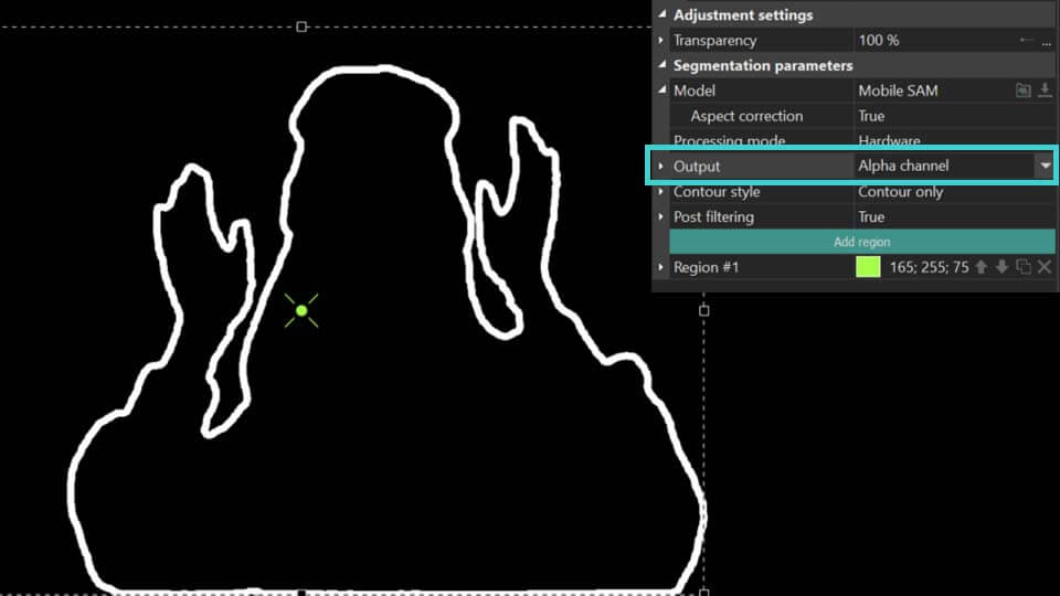
- Contour style: customizes the contour of the segmentation. The following options are available here:
None: no contour displayed
 Contour and object (available for Output = Composite): shows both segmentation result and its contour.
Contour only: displays only the contour.
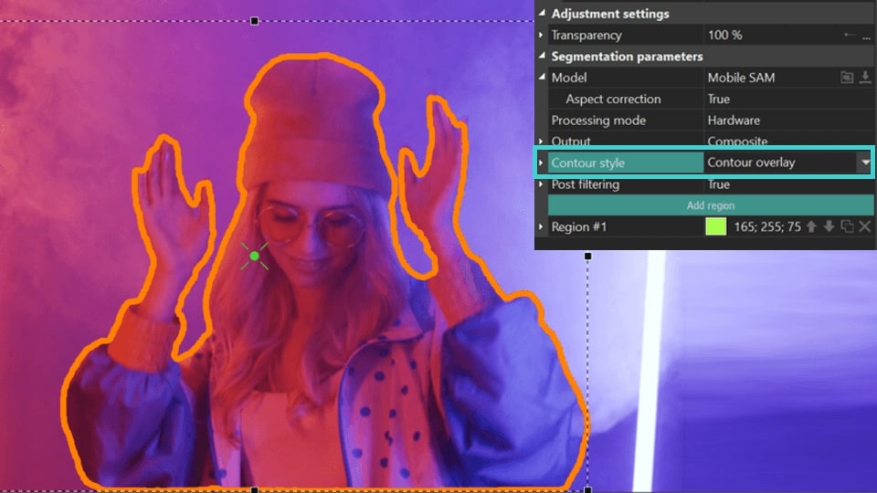
 Contour overlay (available for Output = Composite): shows the contour of the segmentation on the original object in the preview window .
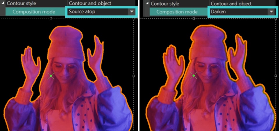
- Composition mode (available for Contour Style = Contour overlay, Contour and object): offers various styles for contour display including Destination over which builds contours at the segmentation edge without extending into the object boundaries, Source atop where contours directly overlay the segmentation, Darken which constructs the contour along the edge and creates a subtler duplicate inside it, and more. Experiment with these styles to find your preferred look!
Destination over
Source atop and Darken: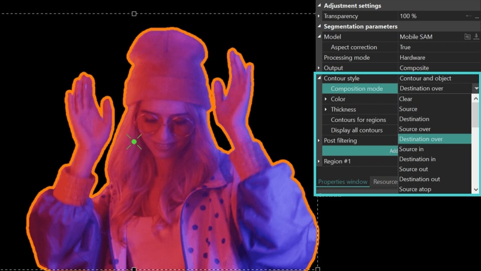
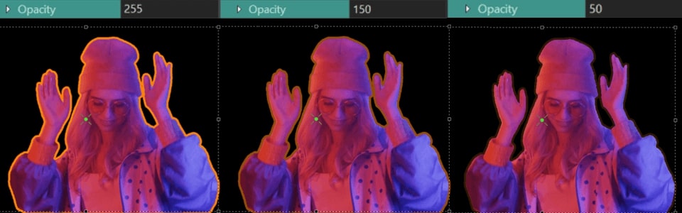
- Color (available for Contour Style = Contour overlay, Contour and object): sets the contour color for all segmentation regions on the scene and includes two additional parameters:
RGB Color: helps to identify the exact color code or modify it to a new one.
Opacity: adjusts transparency of the contour: if set to 255, it means fully opaque contours, if set to 0—fully transparent. Here you can also set the Initial/Final value for the contour transparency at the beginning/end of the display.
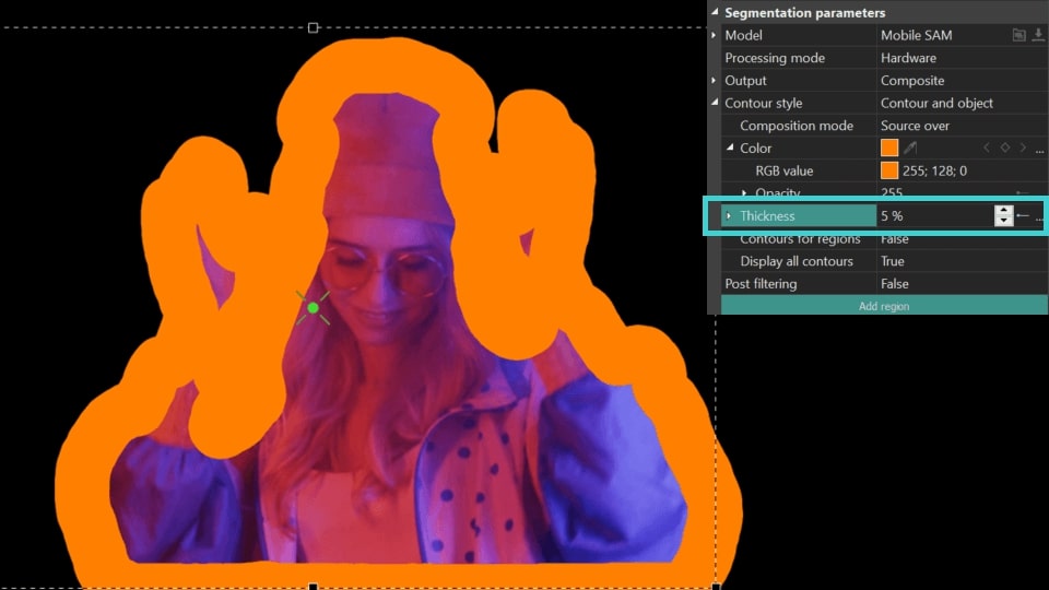
- Thickness (available for Contour Style = Contour overlay, Contour and object, Contour only): sets the thickness of the contour (calculated in % of the length of the edited object, the range is from 0% to 10%). Here you can also set the Initial/Final value for the contour thickness at the beginning/end of the display. ).
- Fill background (available for Contour style = Contour only, Contour overlay): fills the area inside the contour with the contour color .
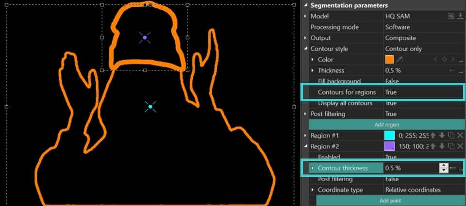
- Contours for regions: adjusts contour thickness separately for each region individually. When set to True, an additional Contour thickness option appears in the individual region settings.
NOTE: if you previously adjusted the contour thickness using the Thickness option described earlier, it will double your values when modifying individual region settings. Therefore, it's recommended to set it to zero.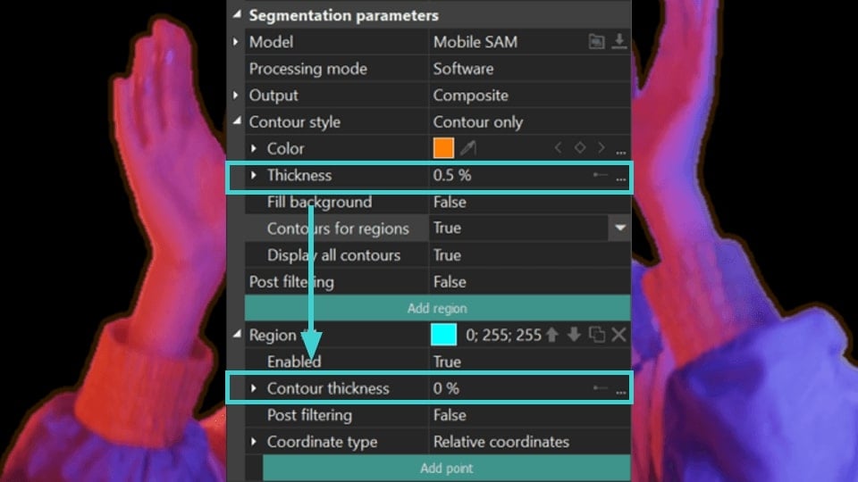
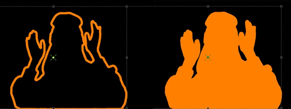
- Display all contours: enables drawing contours for all areas found, otherwise only for the largest area. To use this parameter, it is recommended to switch to Alpha channel for more accurate segmentation.
This tool ensures accurate segmentation: when Display all contours = True, the program highlights/overlays all the smallest points of the original edited object in the segmentation region not removed during the segmentation process. Upon identifying these details, you can refine the segmentation by excluding them with special points. For more details on these points, refer to the section Setting Up Points to Refine Segmentation Regions.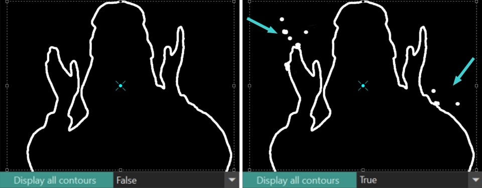
- Post filtering: fine-tunes the segmentation contour across all regions. When set to True, the following tools become available:
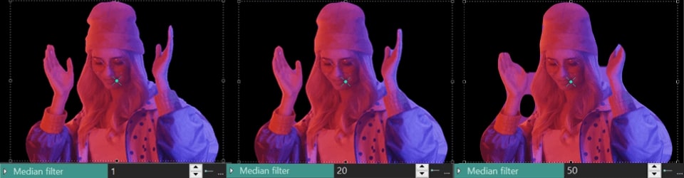
Median filter: smooths the contour by removing noise. Here you can also set the Initial/Final value for the contour filter at the beginning/end of the display. The higher the value of this parameter, the smoother the contour.
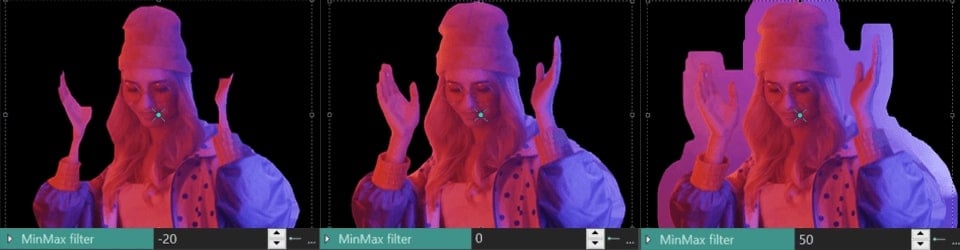
 MinMax filter: adjusts the size of the segmentation area in pixels. Positive values increase the area around the segmented region, while negative values decrease it. The Initial/Final value for the contour can be adjusted at the start and end of the display.
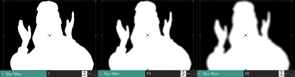
 Blur filter (available for Contour Style = None/Contour and object): blurs the edges of the segmented region . Here you can also set the Initial/Final value for the contour filter at the beginning/end of the display. The higher the value of this parameter, the wider the blur contour.
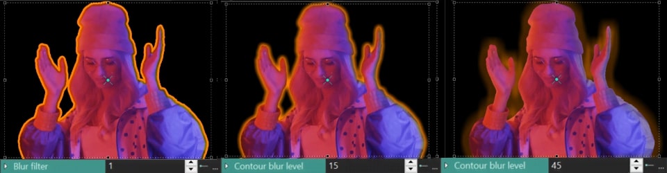
 Contour blur level (available for Contour style = Contour and object): blures only the outline of the segmented area without affecting the edges. The Initial/Final value can be adjusted at the start and end of the display to control the level of blur.
Adjusting Segmentation Regions
This section allows precise management of segmentation regions using the following icons under the Add region button. The primary option is Region, which allows you to modify several segmentation settings at once:
- Color: a square, colored icon that sets the color value for a particular segmentation region, displayed in the center of an area.
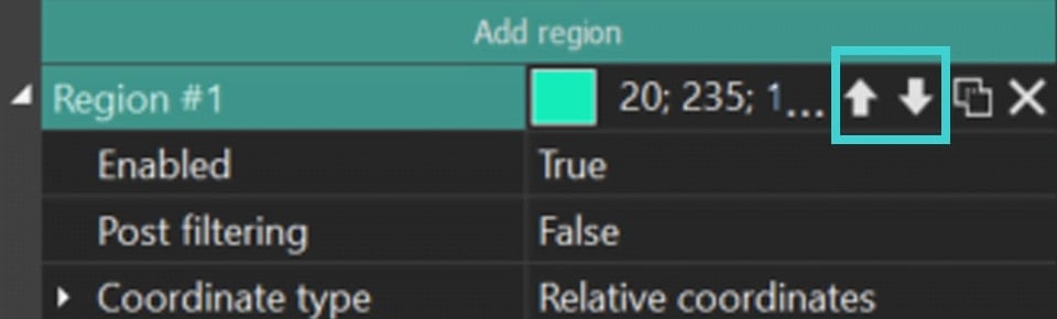
- Region level: two arrows (up and down) that adjust the sequence of segmentations to move a region higher or lower in the list.
- Changing region modes: an icon with two squares that switches between the Exclude region and Include region modes for each segmentation region.

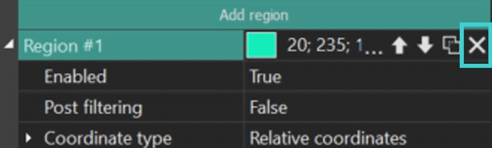
- Delete region: an icon with cross that removes an unnecessary segmentation region.
Expanding the Region menu reveals additional options, each detailed below:
- Enabled: activates or deactivates a specific segmentation region.
- Contour thickness (available for Contours for Regions = True): adjusts the thickness of the contour in a selected region. It also features a hidden menu that allows for modifying the Initial and Final values separately.
- Post filtering: refines the contour of the segmentation result of a particular region. Options include Median filter, MinMax filter and Blur filter, as well as two additional options:
Contour blur level: applies a blur effect to the contour with options to set Initial and Final values.
 Threshold: sets a threshold value for pixels in a particular segmentation region. If a pixel has a value lower than this threshold in the selected region, the program "excludes" this pixel from the segmentation result of a particular region.
The modes are:
- None: the Threshold parameter is disabled.
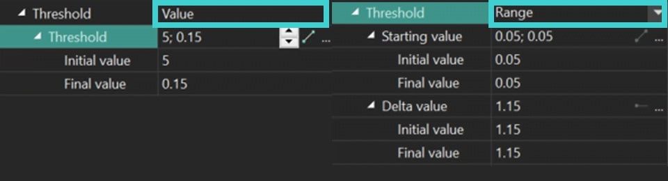
- Value: sets a precise Threshold value and adjusts the Initial/Final Threshold values as needed.
- Range: A more refined mode that uses the Starting value option to limit each pixel in the segmented object, thereby affecting the effectiveness of object detection. The lower the Starting value, the better the object detection, as it essentially indicates the colors in which the object is found. The Delta parameter smooths transitions between pixels if there is a stark limit set by the Starting value.
- Coordinate type:
- Relative coordinates: defines how coordinates are set for a particular segmentation region:
- Left / Right: sets vertical sides as percentages of the object's length.
- Top / Bottom: sets horizontal sides as percentages of the object's width.
Here you can also set the Initial/Final value for the vertical/horizontal value at the beginning/end of the display.
- Whole Image: applies segmentation to the entire object without adjusting coordinates, using points added through the Add point button to find objects for segmentation. The process of working with points in this mode is identical to the one described below, while the search for objects will be performed around the Include point, and with the help of Exclude point you can "cut off" unnecessary/faulty areas.

- Relative coordinates: defines how coordinates are set for a particular segmentation region:
Setting Up Points to Refine Segmentation Regions
Another tool for refining a particular segmentation region is the refinement points. To start working with them, go to the segmentation region in the Properties window in which you want to implement the refinement and click on the Add point button. In the drop-down menu, select one of the positions:
![]() Include point: the area around the added point will be included in the segmentation result of this region.
Include point: the area around the added point will be included in the segmentation result of this region.
![]() Exclude point: the program will cut out the area around the added point (including it) from the segmentation results of the region.
Exclude point: the program will cut out the area around the added point (including it) from the segmentation results of the region.


In the menu that appears, you will see the Point field where you can also adjust settings such as changing the point's color, modifying its mode, or deleting it. If you expand the Point menu, you can access additional settings such as:
- Enabled: allows to enable (=True) or disable (=False) a specific refinement point.
- Coordinate type:
Relative coordinates: allows to manually adjust the coordinates for a specific refinement point on the X and Y axes, where with the Initial/Final value X / Y is the coordinate value at the beginning/end of the display.
Tracking point: segments an object during some video clip. Below we consider this option in details.
How to Use Tracking Points for Segmentation
- To begin, locate the segmentation object on the timeline and hide it using the eye icon located to the left of to display the object without any modifications.
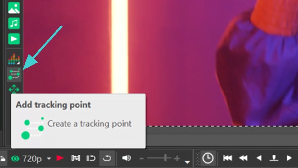
- Select the Add tracking point option from the vertical toolbar menu on the left side of the scene and set this point on the object you want to track.
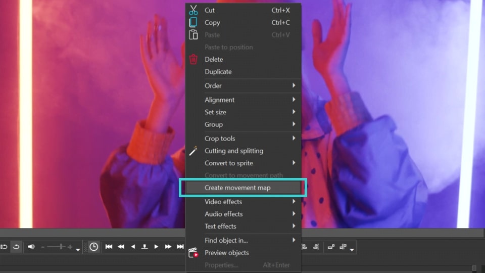
- Right-click on the preview screen to open the drop-down menu and select Create movement map. In the window that appears, give a name to the future motion map and save it.
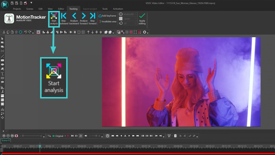
- In the new Tracking window select the region where the object you want to track is located. Then click on the Start analysis button, and the program will create a motion map of the selected object. If you are satisfied with the result, click Apply editing.
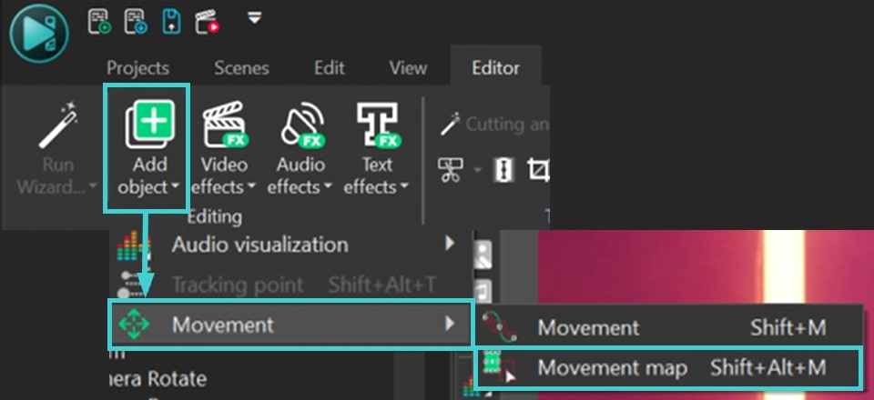
- Double click the Tracking Point object on the timeline, go to the Editor tab and click Add object >> Movement >> Movement map. This will apply the movement map you created to the point.
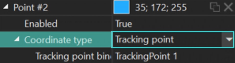
- Reveal the Segmentation object on the timeline by returning the eye icon on the left side of the layer. Then go to the segmentation Properties, find the point to which you want to apply Tracking point and set Tracking point in Coordinate type.
Export Your Project
As soon as you are satisfied with the result of segmentation, go to the Export project tab and select the desired format on the Ribbon. Select the Profile and adjust export settings (if necessary) and click the Export project icon above the scene. To learn more about exporting files, check out our video guide.
NOTE: the segmentation feature is quite resource-intensive, so we recommend using hardware acceleration on the export stage. For this, you need to upgrade to VSDC Pro.
Conclusion
AI segmentation is an innovative tool designed to enhance your video projects. Experience it by upgrading to Version 9.2 of VSDC Video Editor. Follow our latest news on Facebook and X, and subscribe to our Youtube channel. For any assistance, reach out to us at This email address is being protected from spambots. You need JavaScript enabled to view it.—we're always here to help!
© 2011-2024, www.videosoftdev.com, FLASH-INTEGRO LLC. Privacy policy | Terms of use | About us
All trademarks referenced herein are the sole property of their respective owners.
Copying any materials from this site allowed only with written consent of Site Administration.